First, the basic principle of servo valve feedback correction
The core of servo valve feedback correction is to form closed-loop control by collecting the feedback signal of spool position or output flow in real time and comparing it with the target instruction, so as to correct the control signal and make the spool position closer to the set value. Common feedback methods include position feedback, pressure feedback and flow feedback.
Proportional-Integral-Differential (PID) control algorithm is usually used for feedback correction. By adjusting PID parameters, the system oscillation can be effectively suppressed, and the response speed and control accuracy can be improved. In addition, intelligent control methods such as fuzzy control and neural network control in modern control theory have also been applied in high-precision servo systems.
Second, the implementation steps of servo valve feedback correction
1. Sensor selection and installation
The premise of implementing feedback correction is to obtain the state information of servo valve accurately. Usually, displacement sensors (such as LVDT), pressure sensors or flow sensors are used for measurement. The sensor should be installed as close as possible to the actuator to reduce signal delay and interference.
2. Signal conditioning and acquisition
The analog signal output by the sensor usually needs to be filtered, amplified and analog-to-digital converted before being sent to the controller. High-quality signal processing is the basis of accurate control.
3. Controller design and parameter tuning
Controller is the “brain” of feedback correction system. According to the system requirements, the appropriate control algorithm is selected and the parameters are adjusted to achieve the best control effect. For example, using Ziegler-Nichols method, self-tuning algorithm or model predictive control method to optimize parameters.
4. Closed-loop control execution
The controller compares the feedback signal with the given signal and calculates the error, and outputs a correction signal to drive the servo valve to work, forming a closed-loop control. This process requires high-speed processing and real-time response ability.
5. System testing and optimization
After the initial calibration, the system performance should be tested, including response speed, steady-state error, anti-disturbance ability and other indicators. Further optimize the control strategy and parameter settings according to the test results.
Third, the application case and effect analysis
In a hydraulic servo control system, because of the nonlinear hysteresis of the servo valve, the response of the system lags behind and the accuracy decreases. By introducing the position feedback and PID control algorithm based on LVDT, the response time of the system is shortened by 30%, the steady-state error is reduced from 2% to 0.5%, and the control accuracy is significantly improved.
IV. Conclusion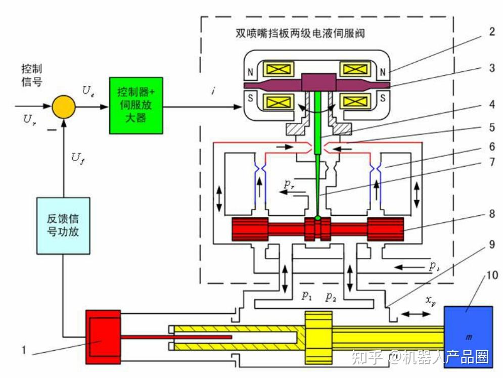
With the continuous development of automation technology, servo valve feedback correction has gradually developed from traditional PID control to intelligent direction. In the future, the combination of digital signal processing, embedded technology and artificial intelligence algorithm will further improve the control performance and adaptability of servo valve. For engineers and technicians, mastering the implementation method of feedback correction is not only the key to improve the system performance, but also an important way to promote the technical progress of high-end equipment manufacturing.